After completing my Siemens PLC training in Pahang, I was employed by FGC (Fuji Global Chocolate) on the 4th of November 2024 as a Maintenance Executive (Automation & Calibration). A couple of weeks into my tenure, my manager assigned me a task to implement a safety interlock during product transfer between tanks (from the Melter tanks to Tank A or Tank B).
Planned SOP
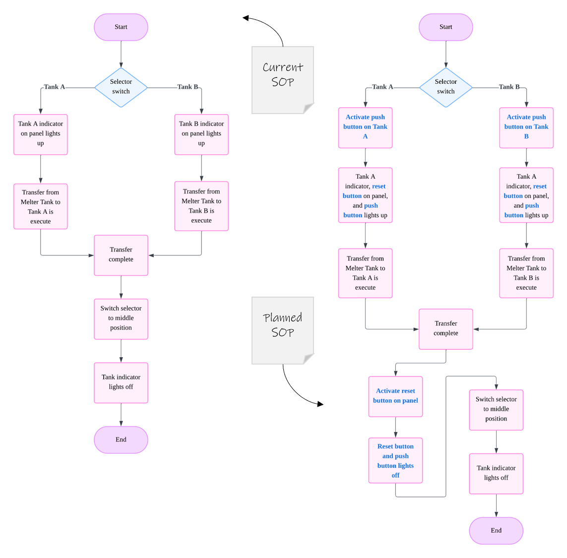
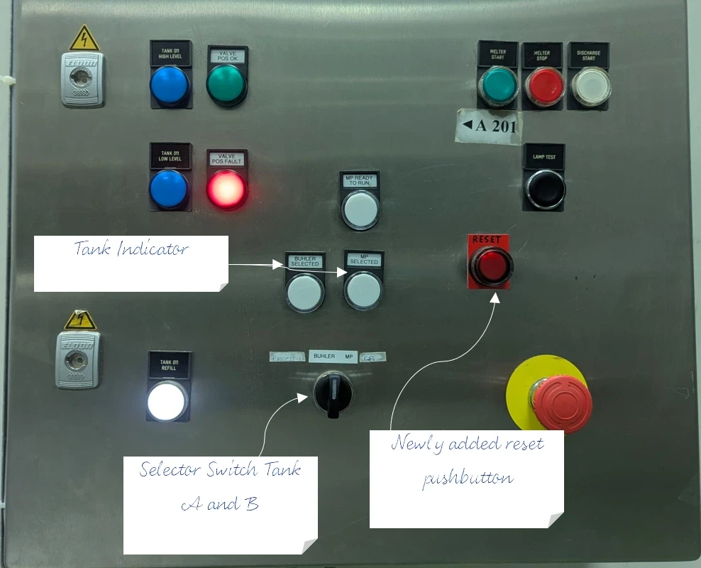
The current SOP above shows that no safety interlock was present in the current control system if the operator were to misoperate the selector switch. The proposed solution was to separate the selector switch and the relay using another relay, which is energized by activate a pushbutton at the respective tank.
There are two key points regarding the updated SOP.
- The newly added pushbutton serves as an additional safety confirmation for selecting the correct tank.
- The newly added reset button acts as a safety confirmation before starting a new transfer while also resetting the second relay, since a latching type relay is used in this design.
Design & Simulate
For simple project like this one, I like to use Festo FluidSim to quickly design and simulate control logic before implementation.
Implementation
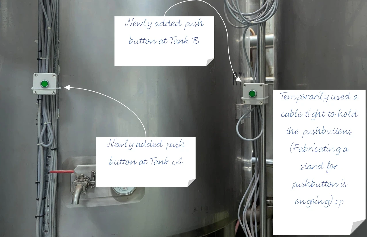
Once the control system design was approved, the next step was to proceed with the wiring. See below for the completed work on the tank and the control panel.